An Overview on Rheostats
Rheostat Overview – Construction and Working, Different Applications
Rheostats are resistors which are adjustable, and are used when applications require current adjustment or different resistance in an electrical circuit. Rheostats can adjust generator features, low lights, and start or stable the speed of electrical motors.
There are two things that affect the amount of current flowing into an electric circuit: the magnitude of the applied voltage and the overall resistance of that circuit. If the circuit resistance is lowered, the electric current flow that is passing through the circuit increases. Conversely, the electric current is limited if the circuit resistance is increased.
There is direct relation between the length of the wire to the resistance of the circuit. Increasing the length of the wire increases the resistance between in the circuit. Rheostats allows resistance to be changed, which in turn, either increases or decreases the current through the circuit. The need to add different resistors for varying resistances automatically disappears since a single rheostat can incorporate different resistances necessary for the circuit depending upon its range.
Construction and Working
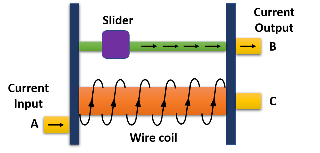
A rheostat is a wire wound variable resistor which has two connection points: one is a moving point and the other one is a fixed point. Similar to a potentiometer, some rheostats can have three connection points (A, B, and C) as shown in Figure 1, but still, only two of them are used. In such cases, there are two fixed points (A and C), only one of which is used, and the second connection point is the moving one (B).
Rheostats also have to bear large currents when compared with potentiometers. Therefore, rheostats are made up of wire wound resistors. They are mainly constructed by wrapping the Nichrome wire across a ceramic core. Such a core behaves as an insulator to the heat energy and does not permit it to flow through the rheostat.

Figure 1 Rheostat internal Structure (Linear)
Figure 1 explains the working principles of a rheostat. As mentioned above, rheostats work on the principle that the resistance of a certain track or wire depends upon its length. Let’s assume that we are using the fixed connection point A and the moving connection point B of the rheostat illustrated in Figure 1. The rheostat will offer minimum resistance to the circuit if the slider lies closer to point A, since the resistive coil length is at a minimum. Therefore, a large current can flow through the circuit in this case.
Similarly, the rheostat will offer maximum resistance if the slider lies closer to point C, as the resistive coil length is at its maximum. Hence, a tiny amount of current would flow through the circuit and a large part of the current would be opposed by the rheostat.
Now, let’s say that we are using the fixed connection point C and the moving connection point B. In this case, when the slider is made to lie near point C, the rheostat would offer minimum resistance and maximum current flow through the circuit. Likewise, when the slider is moved near to point A, the rheostat would offer maximum resistance and minimum current flow through the circuit.
Finally, it is important to know the maximum and minimum resistances necessary for your circuit. Rheostats have maximum and minimum resistance ratings, and thus, they cannot offer resistance outside their inherited range.
Now you may be wondering if there is a high point up to which the resistance may be decreased or elevated inside the rheostat. For all rheostats, they come with a resistance rating, for instance if 50kω is the rating of the rheostat, the minimum resistance it will deliver is zero and the maximum will be near 50kω.
Different Applications
Rheostats are used in situations where high voltage is needed to transmit electricity. They either work as a variable resistor or as a potential divider. An example of rheostats working as a variable resistor is in dimmers. Fan dimmers and light dimmers frequently use rheostats to control the variation of speed and the intensity of light respectively.
Rheostats are used to change the intensity of light when the lights are dim. The flow of electric current decreases through the bulb. If rheostats resistance is increased the light brightness is lessened. Similarly, The flow of electric current increases through the bulb. If rheostats resistance is increased, the light brightness is increased.
When the rheostat amplifies its resistance, the electric current through the bulb is reduced and the light dims. This same process would slow a ceiling or portable wall fan. Radios are equipped with rheostats to manage volume. Motor speeds can also be controlled through rheostats. They can also be used to control temperature in an oven, a heater or an apartment.
Rheostats also work as potential dividers. Wheatstone bridge applies the same potential dividing principle. Different types of resistive sensors use the potential dividing technique, strain gauges, light dependent resistors and thermistors. Rheostats can be used to measure the resistance of a sensor through a microcontroller. Rheostats can accomplish high voltage readings as well as accurate logic level shifting.
Rheostats are still a primary and common component to control the discharging of current in an electrical circuit. However, solid state devices like triacs and silicon-controlled rectifiers (SCR) have taken the place of rheostats. Rheostats are less efficient than a triac and are less reliable because of presence of mechanical components.
They are mostly when circuits need to be tuned or calibrated. High voltage power lines also use rheostats as potential dividers. Low current and high voltage induce minimal losses in power transmission. This helps supply electricity to millions of homes around the globe.

